

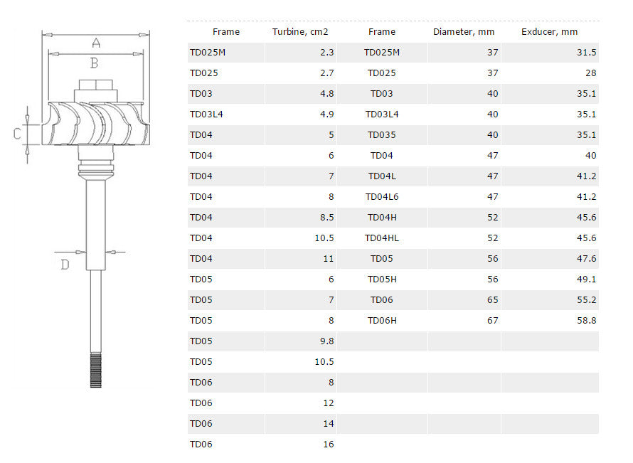
Kinugawa Turbo Systems these days carry the TD prefix followed by a number. the number generally designates the class of turbo and turbine wheel size. The most current models are the TD series turbine wheels.It roughly breaks down into TD generation of turbine wheel, 5H class of turbine wheel (specific size) , 16G compressor wheel, 6CM turbine housing.
1. Turbine housings:
Below is a small chart translating the turbocharger information into more common A/R ratios that we are all used to seeing
these days as used with Garrett turbochargers.
6 cm2 = 0.41 A/R
7 cm2 = 0.49 A/R
8 cm2 = 0.57 A/R
9 cm2 = 0.65 A/R
10 cm2 = 0.73 A/R
11 cm2 = 0.81 A/R
12 cm2 = 0.89 A/R
All TD04 based turbochargers use from 5 to 7cm turbine housings (to my knowledge) and TD05 series turbochargers generally use anywhere from 6 to 10cm housings.
2. Compressor wheels:
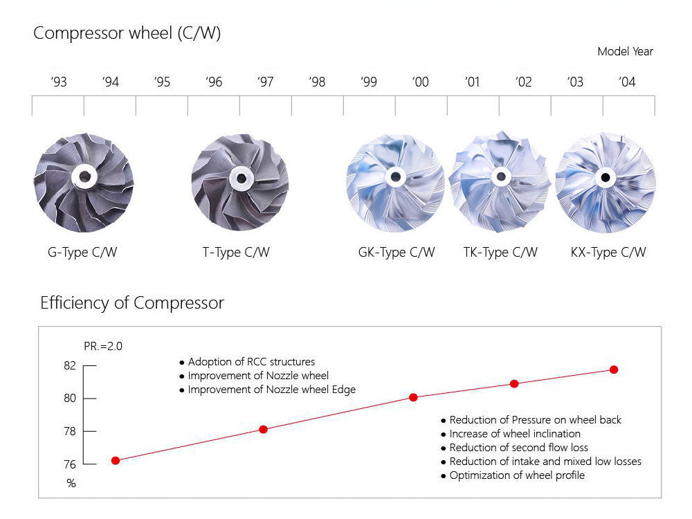
Kinugawa compressor wheels are usually a number joined with a letter. The number is a specific wheel and the letter is the shape or blade arangement (trim). There are G,T,GK,TK,KX series wheels. "G" series compressor wheels are usually alternating blade heights and curvature of the fins, where as "KX" series wheels are all lateset designed with 3rd-order surface point milling.
1. Turbine housings:
Below is a small chart translating the turbocharger information into more common A/R ratios that we are all used to seeing
these days as used with Garrett turbochargers.
6 cm2 = 0.41 A/R
7 cm2 = 0.49 A/R
8 cm2 = 0.57 A/R
9 cm2 = 0.65 A/R
10 cm2 = 0.73 A/R
11 cm2 = 0.81 A/R
12 cm2 = 0.89 A/R
All TD04 based turbochargers use from 5 to 7cm turbine housings (to my knowledge) and TD05 series turbochargers generally use anywhere from 6 to 10cm housings.
2. Compressor wheels:
Kinugawa compressor wheels are usually a number joined with a letter. The number is a specific wheel and the letter is the shape or blade arangement (trim). There are G,T,GK,TK,KX series wheels. "G" series compressor wheels are usually alternating blade heights and curvature of the fins, where as "KX" series wheels are all lateset designed with 3rd-order surface point milling.
- 3D Design and Three-dimensional Flow Analysis.
- The new type of wheel can reduce the impact loss and eddy loss of airflow. Higher compressure ratio and broader flow range available.
- The highest efficiency of Compressor can reach 81.8%

| Free Surface | Ruled Surface | |
| Process | Point Milling | Flank Milling |
| Machining Time | Slow 120 mins.each | Quick 15 mins.each |
| Characters |
1. Free Surface can be only produced by Point Milling |
1. Ruled Surface can be produced by Flank Milling 2. Low efficiency 3. Only suitable to the very easy design of compressor wheel 4. Mainly for fundamental mechanical engineering such as Centrifugal compressor |
3. Turbine wheels:
Any TD04 series compressor wheel will fit on any TD04 series shaft weather its TD04H or TD04HL or even TE04H.
TD04 and TD05 series compressor wheels are not interchangeable because of the size of the hole in the compressor wheel.
You CAN sleeve a TD05 wheel to fit a TD04 shaft but this requires precise balancing and if the compressor wheel is too big.
It MAY cause the shaft to snap a high speeds or wear on bearings un-evenly and cause a failure.

| Turbocharger | T = Exhaust Gas Turbocharger D = Turbo design series (not alphabetical) 04 = Turbine wheel frame size H = Optional suffix for enlarged diameter: |
| Compressor | 08 = Compressor size: At the highest efficiency on the compression line ratio π = 2, the air flow is 0.08 m3/sec. T = Compressor Wheel design type (not alphabetical) |
| Turbine | H = Optional suffix for wheel width: S = small M = medium L = large R = Optional suffix for reverse rotation direction 6.5 = Turbine Housing throat area = 6.5 cm2 (this is the dimension A in A/R) or VG for Variable Geometry or total area plus suffix T/S for Twin Scroll housing |
| Hybrid Turbocharger | When using a Compressor wheel from another Turbine series, it is called a hybrid Turbocharger, for example : TD04-04H*13T-6.5 T/S In this example a 13T compressorfrom the TD04H series is combined with a TD04 series turbine. |
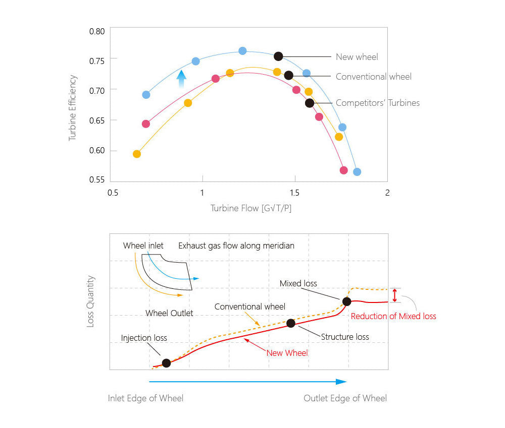
- 3.1 Turbine Wheel Characteristics
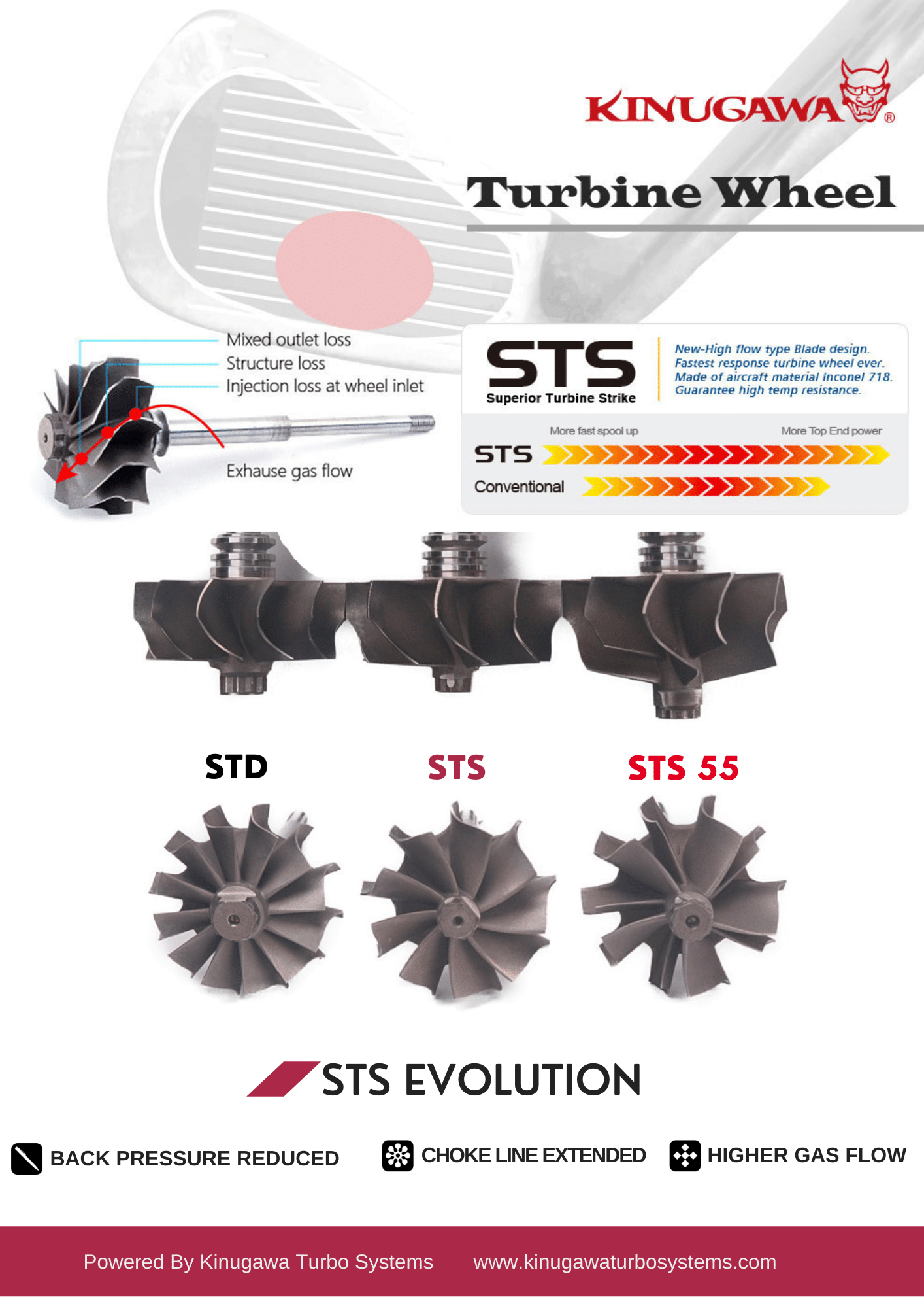
- 3.2 Superior Turbine Strike
The STS (Superior Turbine Strike) turbine wheel will take a shorter time (a 5-8% decrease) to build boost, achieve higher top-end speeds, and extend the choking area. This is because it has less inertia and restriction compared to an 11 or 12-blade STD turbine, and it also has more flow capacity. The STS 55 turbine wheel improve from STS, inspired by cutting-edge turbine aero, employs a patent-pending splitter-blade design to achieve unprecedented levels of flow capacity and efficiency. This translates to a significant reduction in exhaust manifold pressure (EMAP) by operating at a reduced expansion ratio, unlocking a multitude of performance benefits:
- Unleashed Engine Power: Reduced backpressure, a direct result of the lower expansion ratio, allows your engine to breathe freely, resulting in a substantial boost in horsepower and torque.
- Enhanced Volumetric Efficiency: Lower EMAP, achieved through optimized expansion, improves the engine's ability to ingest air and fuel, contributing to heightened responsiveness and overall efficiency.
- Reduced Knock Sensitivity: Lower EMAP mitigates the risk of detonation, permitting more aggressive tuning and further power extraction.
- Cooler Engine Operation: The optimized expansion ratio contributes to lower exhaust gas temperatures, alleviating thermal stress on your engine and enhancing reliability.
The STS 55's innovative splitter-blade design transcends the traditional trade-off between flow capacity and efficiency. By refining blade loading and minimizing blockage in the throat area, it achieves the high flow of a low blade-count turbine while maintaining the efficiency of a high blade-count configuration.

The STS Advanced (Ceramic Dual Ball Bearing 9 Blades) enhances the STS (Journal Bearing 9 Blades) that improves the response speed (time needed to build boost) 10-15% as well as being more durable due to the improved shaft dynamics control. The increased power comes from the enhanced design. It utilizes an inner and outer race with rollers or balls between the two races. The inner race is pressed onto the turbo shaft, and the outer race is pressed into the CHRA. The rollers or balls replace the oil’s “job” of controlling the turbo shaft’s orientation but do still need to be lubricated.

4. Compressor Maps

5. Enhanced Internal Spare Parts:
 |
 |
| The CFD design of the turbine wheel meets the exhaust, thus increasing gas flow, reducing back pressure, and lowering temperatures, allowing a safer, higher boost level. This process also gives the advantage of removing one material, lightening the turbine wheel, thus reducing rotational mass and improving the moment of inertia. | The 360 degree design performance thrust bearing kit, It's durable at heavy loads without loss in transient response. |
6. Crank Horsepower Range:

* * * Size A3 Download / Size A4 Download
2 comments
Sorry the STS turbine codes are hard to understand. The x2 codes are STS and STS55. Aside from the number of turbine blades between these codes, does this mean that STS is standard and STS55 is the STS advanced version with the ceramic ball bearings? Or are both STS and STS55 codes using Ceramic ball bearing technology and both classed as advanced? I guess its not clear to me which code is STS advanced? If you can help clarify please. Thanks
This is great info. Is there more data about the TD06SL2 16g 18g 20g and 7cm 8cm. Is there turbo maps for the TD06Sl2 lineup?